History of GASPACS
Summary[edit | edit source]
The Development of the Cubesat GASPACS (Get Away Special Passive Attitude Control Satellite) is unique in the world of cubesats. The programs uniqueness is derived primarily from the team charged with its development. The Utah State University Get Away Special Team is a team made up of undergraduate volunteers, with little too no in engineering or aerospace experience. The majority of cubesat programs developed by students are run in conjunction with senior design programs, graduate level research programs, or a professional organization. In addition it is rare for a team to develop the entire satellite. Most often a team will develop a payload, and another the main bus, and another integration testing, and flight control. Therefore the true uniqueness of the project is clearly shown, an entire cubesat program developed and run by inexperienced undergraduates of the get away special team.
The Fallowing is a brief version by version history of the gradual development of the GASPACS paylode, mission, and vehicle during the years of 2004-2015. It does not include specific testing results or every change to the design, but simply shows a general progression of team effort and design focus.
Timeline[edit | edit source]
2004[edit | edit source]
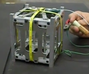
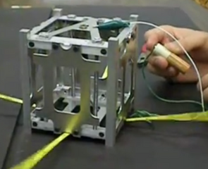
The team initially proposed and began work on a cube satellite concept named Sputnik. The design produced a simple structure similar to the ISIS CubeSat structure, including one aluminum structural face of the CubeSat cut as an A (5656as a reference to the Utah State Aggie A), a communications board out of a partial HAM radio, a rather innovative "measuring tape" deployable antenna system (successful deployment of the four antennae via battery was achieved), and a main command board from a simple micro controller. The project was abandoned in favor of a micro gravity experiment and other, more pressing projects.
2010[edit | edit source]
LEOP (Low Earth Orbiting Photographer), the first of the LEOP series CubeSat designs. Its theoretical design included a 1U earth pointing CubeSat with a camera to photograph large earth features, such as islands and polar ice caps. The solar panels were to be made in-house. The communications board was to be a repurposed HAM radio. The main flight computer was to be a STM32 Discovery Microcontroller board. The main flight camera was to a repurposed USB camera with a Xenon Optics wide angle lens. The batteries, antenna, and structure were to be the same as the earlier CubeSat project. The basic mission concepts were based around the CubeSat recognizing it was facing the light side of the earth (day-time) and taking pictures along its orbit. Preliminary design review, conducted by members of SDL, found the design to be inconsistent between different sub-group teams, and incomplete definition and scope of CubeSat parts and development. Also the mission to photograph features of the earth while in orbit would likely fail due to the lack of ADCS control.
2011[edit | edit source]
LEOP Version 2[edit | edit source]
Learning from the mistakes of the first LEOP, the team addressed ADCS problems in order to accomplish the photography mission. Initially the GOM Space solar panels with magnatourqers and the nanomind were thought to be sufficient attitude control to the CubeSat to maintain the earth-facing camera orientation. However, active control of a CubeSat turned out to be more expensive, power hungry, and complicated than the team was prepared to undertake. As a result, passive attitude control methods were researched in an attempt to find a simple solution to the attitude control problems. Permanent magnets were first considered for their simplicity and flight history, however using MATLAB simulink software it was found as the satellite, which would likely travel in a non-equitorial orbit, would likely tumble as its orbit crossed closer to the poles due to the shape of Earth's magnetic fields. Histeresis materials were then considered for primary flight control. However their properties could not explicitly orient the CubeSat in any direction. Finally, utilization of the gravity gradient effect was considered. Although it likely would include a complicated deployment mechanism, in order to move and tether a mass a specific distance away from the CubeSat, it was decided the gravity gradient effect would provide the desired attitude control and allow for the successful completion of the photography mission. The team first developed a spring tape deployable boom concept. The concept of the mission included the spring tape, under it’s own power, release and extend a 1 meter long boom. Once extended the CubeSat would take a picture to verify its orientation. If the earth was not in the photograph, the boom would be recovered with the use of electric motors and allowed to redeploy in a different orientation. Other improvements from the PDR included a clamshell type structure. This in theory would allow the CubeSat to be assembled faster and easier than the previous structure. Other topics addressed were power, thermal, and vibrational analysis.
LEOP Version 3[edit | edit source]
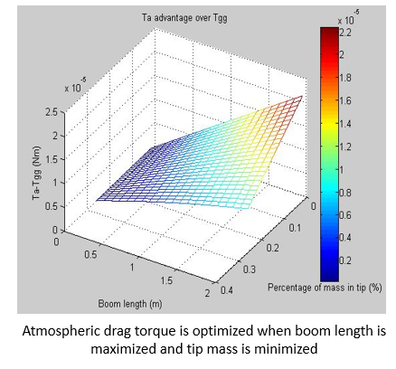
As the LEOP design progressed it was discovered the primary computer, the STM Discovery board, would not fit without drastic modifications. Therefore a new primary computer would be needed. The nanomind from GOM Space and The Pumpkin flight computers were considered. After substantial research the nanomind was selected the main flight computer. The team chose the nanomind due to its already integrated ADCS capability. The flight camera was determined to be unusable due to overly complicated USB protocol. The GG boom retraction capability was dropped as it would be mechanically large and complicated for any reasonable type of reliability. Instead the mission would use on board sensors and deployment algorithms in an attempt to deploy the boom with the correct orientation. In the event the boom was deployed in an incorrect orientation, the mission would change from photographing the earth to photographing stars. As a result an algorithm to determine attitude using stars was also reasearched. Through a series of design reviews, which included meetings with John Elwell, and a preliminary design review with SDL, the design was determined to be insufficient for a successful completion of the photography mission. Primary causes were sighted as inconsistent design, overcomplicated and untested design features, unrealistic and unnecessary design constraints, and poor understanding of space photography. Even with a perfectly oriented CubeSat, with zero roll rates along any axis, the CubeSat would still be moving 7-8km per second. Considering the optics, camera and the required exposure time, all images produced by the CubeSat would be smeared. Active controls would be necessary to allow the CubeSat to point consistently at a given location in space for the required exposure time. Thus, passive attitude controls were unsuitable for the space and earth photography mission. In addition, further analysis of the GG effect in LEO (approx. 325km) showed in order to overcome other disturbing torques, namely, aerodynamic drag, the CubeSat would require a 14 meter long boom. This would be impossible given the volume and mass constraints of the CubeSat.
2013[edit | edit source]
LEOP Version 5[edit | edit source]
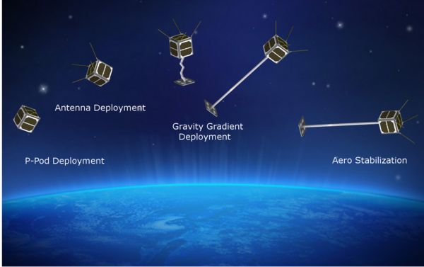
Given the findings from the design reviews and passive attitude control analysis the team decided to make drastic design changes. The photography mission would likely be impossible due to designed constraints and technical capabilities of the team, and the mission was cancelled. Instead the team enacted a new mission based around the GG effect on CubeSats in LEO and therefore the mission was chosen as a technology demonstration of a 1 meter inflatable GG boom from a 1U CubeSat. The inflatable gravity gradient boom, which would be impregnated with a UV curable epoxy, would be released and deployed while in orbit. When exposed to the sun the boom would harden in to a ridged structure. This mission would not require specific orientation control of the CubeSat which greatly simplifies the design and overall development process. Additionally, a technology demonstration of inflatable structures would qualify as a NASA critical technology list.
GASPACS (Get Away Special Passive Attitude Control Satellite)[edit | edit source]
In an attempt to move the system design forward GOM space hardware was chosen by the team as the primary power, computing, and communication boards for the satellite. Unifying the design around these boards accomplished several critical things:
1. Allowed further development of structure, power budgets, COM budgets, mass, and volume, all of which were stuck in design loops (waiting on one part to be chosen so others could be chosen but the first part could not be chosen without knowledge of the others, ect).
2. Unified design allowing for simplified integration between boards. ( This should be noted as a huge determining factor for using GOM space. As GOM space sold all of the boards designed to work together with the same software and protocols running on all of them, the risk was much lower working with the GOM space as opposed to trying to integrate boards from different companies)
3. Simplified design instead of inventing or creating new boards.
4. Focused development of the boom deployment system.
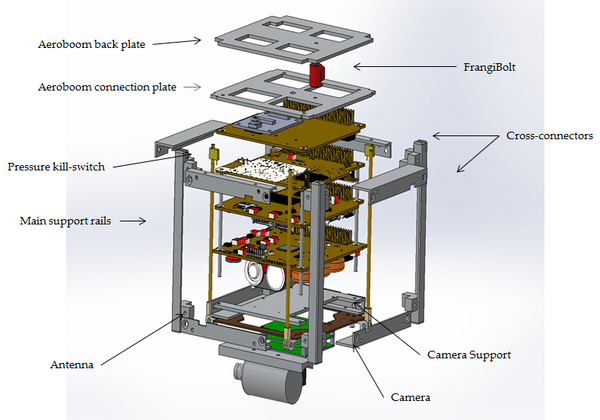
It was determined that the most efficient way to evaluate and verify the deployment of the gravity gradient boom was by means of a camera. The camera would shoot pictures through the Gravity Gradient storage bay as the boom deployed. Other design changes included a frangi bolt from TINI aerospace, which would release a retaining back plate allowing the boom to inflate. A tank of air at 1ATM, for inflation of the boom, sat lower in the CubeSat to the side of the batteries. A solenoid was placed on the opposite side of the batteries. When the CubeSat was ready to deploy the boom, the frangi bolt would be actuated, releasing the boom, then the solenoid would activate and lock in the open position allowing for the inflation of the boom.
2014[edit | edit source]
GASPACS V2[edit | edit source]
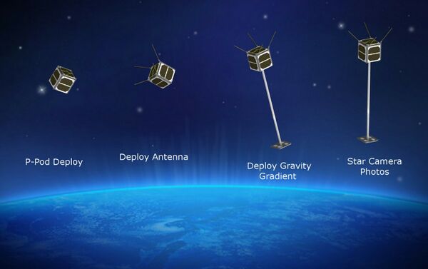
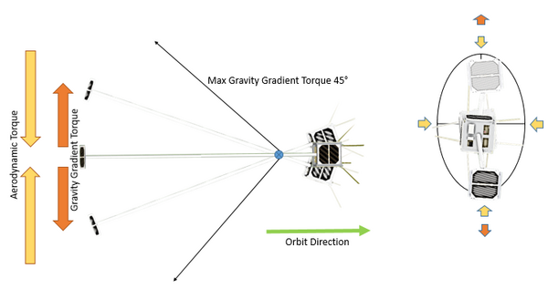
In an extensive effort to identify a camera system suitable camera for the GG boom, a camera system from SDL was found, which would allow for two cameras. The first camera would video the boom deployment, the second would be a star camera for attitude determination. The integration board, which controlled the cameras, would also include software to calculate the attitude on board using the star camera, a GPS unit, a 3 axis gyro, and magnetometers. This “science board” would supplement the ADCS capabilities of the GOM space units. After completion of initial testing and meetings with SDL, the tank and solenoid were determined to be redundant and unnecessary. Residual pressure from the boom was determined to be enough to fully inflate in the vacuum of space. An added bonus to the removal of the tank and solenoid was a more simplified design. However the boom itself would now have to be qualified by NASA safety standards. At this point the team began to focus on the attitude control issue of a deployed boom. It was discovered previously the gravity gradient effect was not enough at the predicted altitude of 325-350km to maintain passive control. At that altitude the dominating effect was found to be aerodynamic drag. As the CubeSat orbits the earth, the drag of random air molecules colliding with the extended back panel will cause a stabilizing effect. Therefore the CubeSat will travel pointing towards its velocity vector, balanced between the aerodynamic and gravity gradient forces. Aero drag models were developed in order to more fully understand and predict the amount of control available. In the end it was found that given the configuration of the CubeSat the gravity gradient effect, and aerodynamic drag effect would fight one another. The aerodynamic drag would force the CubeSat to orient to its velocity vector. The gravity gradient effect would force the orientation to the nadir vector. The net effect on the system would cause the boom end of the CubeSat to oscillate, being forced out of alignment with the velocity vector by the gravity gradient effect, only to be forced back into it by the aerodynamic drag effect. Over time as the CubeSat is buffeted by the different forces the boomwill oscillate in a elliptical manner. Measuring the excentritys of this ellipse will allow the team to back out the strength of the gravity gradient and aerodynamic forces at play during the flight. Although the primary mission remained the technology demonstration, investigating drag and gravity gradient effects was selected as a secondary science mission. The Gravity Gradient Boom was also renamed AeroBoom in reference to this effect.
El-AnA Flight Approval[edit | edit source]
Following an SDL lead Preliminary design review the team wrote and submitted a flight request to NASA El-AnA launch services program. The flight request was approved by NASA.
GASPACS V3[edit | edit source]
As more information was acquired about the boom design the storage bay was increased the from its original 10mm depth to 14mm in order to better fit the folded boom materials and the fittings for the frangi bolt. At this point the antenna was moved from the bottom to the top of the CubeSat. This was to accommodate the NanoAccess ( exterior board which allows access to the interior boards via USB when ready for flight, it also includes charging circuitry and remove before flight pins), which was not originally included in the design. The movement of the antenna to the top of the CubeSat forced the boom to deploy through the antenna structural hole. An additional board was added to interface the camera with the main science board. In-order to remove complex electrical wiring the top and bottom of the CubeSat the solar panels were removed. This would mean only four side solar panels would be available to provide power to the system. Using SDL algorithms and Satellite Tool Kcit software it was determined GASPACS would produce 0.98 W of power per orbit, nominally. The star camera was removed from the design in order to save on power, volume, and simplify the design. The development team was experiencing issues integrating two cameras while locating suitable optics which could fit inside the CubeSat. The missing star camera allowed for the GPS to be mounted on the outside of the CubeSat on the bottom panel.
AeroBoom Materials Selected[edit | edit source]
The team faced significant difficulties identifying, procuring, and sealing materials for the inflatable boom system. The favorite outer protective layer material was Teflon. Teflon was desirable because it was low out gassing, strong, reacted well to UV light, easy to procure in premade tubes, and was not effected by different chemicals as much as other materials. ( other materials considered at this time were kapton, mylar, and polyurethane) However the team did not have access to heat sealing technology hot enough to seal the ends of the Teflon tubes. At length the team discovered a method of using vacuum seal putty, and squishing the Teflon between two layers of G10 glued together with epoxy. The final design resulted in a three layer system, an inner and outer layer of Teflon surrounding a middle layer of fiberglass impregnated with adherent technologies ROC UV curing epoxy, each end to the boom sealed into G10 plates.
2015[edit | edit source]
GASPACS V4[edit | edit source]
After design and management difficulties with SDL, the science board was deselected as the main science and camera interface board. Instead, a simpler camera system was selected. The design included a UART Camera with built in JPEG compression, which could interface directly with the nanomind. In addition the camera would plug into a simple interface board. The frangi bolt was deemed unnecessary after successful testing with a nichrome wire cutter and a Vetran cable system. Additionally the removal of the frangi bolt allowed for a completely unobstructed storage bay, which in turn allowed for a more consistent folding pattern of the boom. The design of the nichrome wire cutters were based off an NRL cutter designed for CubeSat use. The storage bay was reshaped to match the cut out of the antenna. This reduced the overall size of the boom bay, but removal of the science board allowed an increase in depth. Although the storage bay was narrower, the area would still allow for more consistent folding and storage of the boom. Testing showed the boom unable to perform at subzero temperatures and, as a result, heaters were added to the bottom of the bay in order to heat the boom before deployment. As the final design for the AeroBoom payload came into shape and other dimensions became known, work was done to update and assess the assembly method of the CubeSat. It was found that the structure ( still based off the old ISIS model) was significantly out dated. An updated and simplified structure was developed and integrated into the design. The new structure would make assembly far easier and reduced the overall designs part count.
GASPACS V5[edit | edit source]
As the "final" version of the CubeSat the design for the AeroBoom payload was optimized with new circuitry for the nichromwire cutters and camera system, which included a new array of sensors to better elevate the performance of the boom on orbit. The sensors included, separation switch ( to indicate the deployment of the boom), temp sensors for the boom and camera, sun sensors, and pressure sensors for the interior of the boom. An adinial solar panel was fitted to the nanoAccess panel, allowing for more robust power production. A 3D printed model was made in order to verify, fasteners, spacing, and assembly procedures. Thermal modeling using Comsol was developed and successfully verified demonstrated correct deployment temperatures while in space. Cureing and burst pressure tests were conducted validating cure times, and boom failure points too NASA standers.
2016[edit | edit source]
Changes in leadership and student involvement as senior members graduate result in the temporary loss of much information about the progress made in the design of the satellite.
